Bionic Beaver – Setting a static IP address in Ubuntu 18.04.1 LTS

Setting a static IP address in Ubuntu 18.04.1. Oh boy where to start. The name Bionic Beaver or netplan.

OK lets concentrate on netplan, and what’s happened with networking in Ubuntu 18.04.1. Setting a persistent static IP address has changed a little in the new release of Ubuntu, where as before we would have modified the interfaces file we now modify a .yaml file in /etc/netplan directory. Netplan is the new kid on the block for configuring networking in your Beaver. Its not all that different, or difficult once you know how. However the standard is pretty precise in terms of how we configure the file. If you look in your netplan directory you may have a 50-cloud-init.yaml file this is where the configuration is stored. Lets go ahead and modify the netplan directory  to set a static IP address:

This is how our standard /etc/netplan/50-cloud-init.yaml file looks like:

To set a static IP address I’m going to copy the current config into a new file called 01-netcfg.yaml for further configuration.

Take care of the spacing within the yaml file. It will not take tab completion, and will require spaces for the indentation, the number of spaces will not matter, as long as each section is appropriately indented with spaces.

For example you could use this:


Indenting each section with 1 space also works:

All that’s left to do is to apply the netplan config with:

sudo netplan apply

If you do get errors you can use the debug feature:

sudo netplan --debug generate

Well hope this helps.

Traffic Shaping in Linux – controlling your bandwidth

In certain scenarios whilst pentesting there may be a requirement to control your bandwidth from your testing device, otherwise known as traffic shaping. In this post I will walk through how we can do some Traffic Shaping in Linux. All testers should be accountable for the amount of traffic they generate while testing. This is easily achievable in a few different ways, some better than others. I’ll walk through how we can achieve this in this post. It is always a good idea to log and monitor the amount of traffic you are sending and receiving. I will typically do this with ‘iftop’, I will open this before sending any traffic.

iftop looks like this:

Here we can see sent, received and total accumulation in the bottom left.  In the bottom middle are the peak rates. Over to the right hand side we can see the transmission rates for 2, 10 and 40 second intervals. Couple of interesting toggle switches you can use while iftop is open being ‘h’ for help, ‘p’ to display port and ‘s’ and ‘d’ to hide/show source and destination.

On to the traffic shaping.  In most Linux distros Tc (traffic control) is available, this can be used to configure traffic manipulation at the Linux kernel level. Tc is packaged with iproute2 the shiny new(ish) tool set for configuring networking in Linux.

In my view Tc is reasonably complex to configure if you simply need to reduce your bandwidth for an interface. Enter Wondershaper. Wondershaper allows you to limit your bandwidth in a simple manner. It does this using Tc. Wondershaper is available through the Apt repository where Apt is being used.

You can limit your traffic on an interface to 10Mbps upload and download like below. Values are in bits.

wondershaper [interface] [downlink] [uplink]

wondershaper  eth2 10000 10000

To clear the limits set:

wondershaper clear

To see the limits set use:

wondershaper eth2

Testing…

Using iPerf we can test the bandwidth reduction by wondershaper. The setup that I am using for this test is two virtual machines with two cheap physical USB 10/100 Ethernet adapters passed through to each virtual machine and physically connected via an Ethernet cable. Interfaces are set to 100 Full. Running iperf with no restrictions give us the following results:

I’m not surprised by the 55.5Mbits/sec rate.

Throttling our connection to 10Mbits/sec with wondershaper:

Great, we see a distinct change in bandwidth running consistently across 10 seconds lower than 10 Mbits/sec.

Throttling the connection further to 1 Mbit/sec:

And again we see our bandwidth dropping further to less than 1Mbit/sec.

Other ways I have seen been offered up as solutions are turning auto-negotiate off and setting your link speed and duplex. However I would argue this is not traffic shaping. It may work in certain circumstances, however I have had mixed success with virtual machines. This doesn’t give you the granular control of Tc and wondershaper.

Conclusion: A very useful tool for controlling your bandwidth in Linux. For a quick fix use wondershaper for either more granular control dive in and configure Tc manually.

Tunnel snmp-check and other UDP traffic over SSH

Today I will be walking you through how to tunnel snmp-check and other UDP traffic over SSH.

In this example we are tunnelling UDP over SSH to circumvent firewall rules on the outside. Our firewall rules are only allowing access into the other side of the firewall to TCP port 22 on a Ubuntu server. We don’t have access to any other TCP or UDP ports. The only method of communication into the environment is via SSH to our Ubuntu server. We will use this server as jump/pivot point for other traffic. Imagine we have earlier identified through cdpsnarf using SSH dynamic port forwarding and proxychains another router, we want to enumerate this further. Our next goal in this case is to try and enumerate SNMP UDP port 161 on target router with a public community string. This example could also be applied to all sorts of UDP traffic such as DNS for example were we want to tunnel our local DNS requests to a server behind a firewall. Zone transfer maybe?tunnel snmp-check and other UDP over SSH

Attack machine: Kali Linux 192.168.200.2
Pivot Server: Ubuntu 192.168.100.10
Target: GNS3 Cisco Router 192.168.100.100

We are going to do this by sending our local UDP traffic through netcat (handling UDP) into a fifo process back into netcat (handling TCP), through the ssh tunnel then in reverse the other end. Yes I know bit of a brain teaser! You can read more about fifo files here, they are similar to pipe in linux. In essence we are sort of writing the output to a file (without actually writing anything) then sending it on its merry way through netcat via TCP then down the tunnel. Its best we see this in the flesh with an example.

We begin on the Attack machine by running up the ssh connection, here we are forwarding TCP port 6666 on localhost to TCP 6666 on the remote pivot server:

root@kali:~# ssh -L 6666:localhost:6666 user@192.168.100.10

Then on the Pivot Server we create a fifo file for netcat to talk too:

root@ubuntu:/home/user# mkfifo /tmp/fifo
root@ubuntu:/home/user# nc -l -p 6666 < /tmp/fifo | nc -u 192.168.100.100 161 > /tmp/fifo

On the Attack machine we do similar:

root@kali:~# mkfifo /tmp/fifo
root@kali:~# nc -l -u -p 161 < /tmp/fifo | nc localhost 6666 > /tmp/fifo

In second terminal on the attack machine:

Run up ‘netstat -au’ to verify snmp is listening on the local machine.

UDP netstat connections

We can then simple run snmp-check to localhost.

snmp-check 127.0.0.1

snmp-check over SSH


Looking further down the information we discover the following:
snmp-check over SSH another netowrk


Another network interface, is this possibly the internal network and route to DA..? Maybe in the next post…

Bingo UDP and snmp-check over an SSH tunnel, awesome!

VLAN tagging in Kali Linux 2.0

Connecting to Trunked Ports!

Just a quick post on how to configure VLAN tagging in Kali Linux 2.0. If we have a trunk port presented to us, how do we utilise it?

To setup vlan tagging in Kali Linux 2.0 is pretty straight forward, to set the scene and demonstrate this further we need a lab. The below lab is our ‘test.local’ environment set up in GNS3. There are 3 vlans, 10 20 and 30. 10 and 20 are routable, vlan 30 is isolated from 10 and 20. In the lab we have a ‘router on stick’ configured  at R4, fa0/1 is sub interfaced with vlans 10 and 20. utilising DHCP, vlan 10 for servers and vlan 20 for clients. All devices in vlan 30 are statically assigned IP addresses and not routable to the 10 and 20 vlan networks.  In all switches there are a variety of 802.1q trunked and access ports.

The idea of the lab is that vlan 30 can’t talk to vlan 10 or 20. However as a trunked port is presented to the Kali vm, it will be able to communicate to all vlans.

This is how it looks:

VLAN tagging in Kali Linux 2.0 - switch configuration

Lets look at how we would configure Kali to test all hosts in the different vlans, first via CLI and then via GUI in Network Manager:

As you can see with the current trunk connection we can’t access any of the networks, however a quick Wireshark does reveal we can see traffic and the different vlans…

First lets open up ‘/etc/network/interfaces’ in nano and add our interfaces. The idea is very similar to a cisco router we are essentially sub interfacing our network connection in the interfaces file:

An alternative configuration for the interfaces file which I have used as well is the following, both work just as well:

Save our file  restart the networking service and then simply bring up the sub-interfaces with ‘ifconfig XXX up’ where XXX is our subinterface so:

‘ifconfig vlan10 up’ or ‘ifconfig eth0.10 up’ as below:

We can now access all of our vlans in question.

Further to this, if we set off a ping to each network and Wireshark the trunk connection we can see our tagged packets. Hooray.

The Gui is even easier, lets configure it via the Network Manager. We will do this via opening up our network connections/Network Manager, simple click on the ‘+’ sign, select ‘VLAN’ fill in the details on the vlan tab as well as the ‘IPv4Settings’ tab:

And there you have it.

I hope this helps someone!

Active Directory Authentication for Cisco Devices – Routers and Switches

Cisco, AAA, Radius, Active Directory, Windows Server 2012 R2, NAP role, NPS its all going on!

Active Directory Authentication for Cisco DevicesJust a quick note to reference the following video on YouTube. This video demonstrates setting up Active Directory Authentication for Cisco Devices, such as Routers and Switches etc. This is using AAA on the router and RADIUS through the Network Access Policy (NAP) role in Windows Server 2012 R2, this in turn enables a Network Policy Server (NPS). The Windows server (the Radius Server) is registered in Active Directory which allows it to query the domain it is connected too for authenticating users in Active Directory to the Cisco IOS devices. You can control who has access to various network devices through rules created on the NPS. This can in turn be achieved in Active Directory via groups, binding those groups to privilege levels to pass through to deifferent devices.

For example you could have a group in AD called Network Admins which is tied to a prilivelge level 15 group rule in the NPS configuration. This rule would pass through the privilege level 15  setting through to the IOS configuration. Members of this AD group upon succesful authentication would then be granted privilege level 15 access on the router or switch.


PowerShell Port Scan

Check your Egress Filtering with a PowerShell port scan script

Firewall Egress Filtering Check with PowerShell

This is just a quick post so I can refer to myself more than anything regarding conducting a  Powershell Port Scan! However this is a useful couple of lines to to conduct a port scan from a windows device with PowerShell. This can be used in a number of situations however is especially ideal to check your egress filtering out to a server on the internet or to a segmented network. In the below few lines we are testing the first 1000 ports this can be bumped up to 65535 if wanted and the server that you are port scanning is listed as X.X.X.X.

1..1000 | % {$test= new-object system.Net.Sockets.TcpClient; 
$wait = $test.beginConnect("X.X.X.X",$_,$null,$null); 
($wait.asyncwaithandle.waitone(50,$false)); if($test.Connected)
{echo "$_ open"}else{echo "$_ closed"}} | select-string " "

This particular script has been pulled from Black Hills Information Security page here. An alternative from Microsoft’s ‘Hey, Scripting Guy! Blog’ can be found here.

The Common Problem

Often organisations lack adequate egress filtering, by this I mean outbound connects that can be established on a number of ports from within the heart of the network. Client machines and typical internal application servers don’t need to access a range of services out on the Internet. Once a nasty exploit has got an attacker onto a network they will look to get a foothold within the network lateral move and phone home to command and control server. Having a range of ports open to clients and servers allows attackers to make an outbound connects from whole host of tools, including PowerShell for that matter.

The Solution

Check you egress filtering and lock down any unwanted open ports out to the internet, your perimeter firewalls should not allow these outbound connections. Obviously certain services are going to need to make outbound connections such as web proxy and email gateways and these rules should be appropriately provisioned. To take this one step further enable your outbound firewall rules on your local hosts, ‘hang on a sec, you must be crazy’ I hear you say, however by doing this you will be help prevent the lateral movement of attackers through your network as well as being able to get off your network back out to the Internet.

Cisco Access Control List Guidelines to follow when creating rules.

Cisco Access Control List Guidelines

Just a quick post to remind myself and others ofCisco Access Control List Guidelines. the following Cisco Access Control List Guidelines that we should be aware of. I thought this would be good to post as a quick reference/lookup. This just gives a basic run down of how ACL’s should be implemented as per Cisco CCNA Security.

  • Ensure the last ACE that is processed has a ‘deny any’ or ‘deny any any’
  • ACLs are processed top down, as soon as as an ACE is matched the processing is stopped.
  • Make sure the most specific ACEs are at the top of the list.
  • One ACL per interface, per protocol, per direction.
  • Any new ACE’s that are added to an ACL are added to the bottom by default, unless specified.
  • Router generated traffic is not filtered by outbound ACLs
  • Standard ACLs should be placed as close to the destination as possible.
  • Extended ACLs should be placed as close to the source as possible.

Mitigating VLAN Hopping Attacks

Ways to mitigate VLAN Hopping Attacks on a Cisco Switch.

Cisco Switch mitigating VLAN Hopping Attacks

The ways in which we can prevent basic vlan hopping attacks on a Cisco Switch are more best practice security configurations. Vlan hopping attacks can occur in one of two ways. The first by an attacker spoofing DTP messages directly to a switch, if the switchport has Dynamic Trunking Protocol (DTP) enabled it can then negotiate a vlan and receive tagged packets for that vlan. The second is by introducing a rogue switch and again taking advantage of DTP and negotiating a trunk with the switch and then allowing it to receive all vlans. Not good!

We can do the following to prevent this:

  • Disable Dynamic Trunking Protocol (DTP) for non-trunked ports with switchport mode access – this should always be done for all ports straight out of the box!
  • Disable Dynamic Trunking Protocol (DTP) for all trunked ports with switchport non-negotiate.
  • Manually enable trunk ports with switchport mode trunk.
  • Set the native vlan to an unused vlan rather than just leaving it on vlan1 with switchport trunk native vlan (your vlan number)
  • Put all unused ports into an unused vlan and then disable all unused ports – again disabling all unused ports should be done straight out the box.

Configuring IPSec Site-to-Site VPN Tunnels

Configuring a IPSec Site-to-Site VPN Tunnels on a Cisco Router

I thought I would run through configuring IPSec Site-to-Site VPN Tunnels on a cisco router. I’m going to be covering at high level the basic principles needed to configure a IPSec Site-to-Site VPN. The fundemental principals can be used for the Cisco ASA Firewall or Cisco VPN concentrator. The VPN gateways in our example (the routers) are responsible for encapsulating and encrypting the outbound traffic which in a real world example this would from be from a site to a peer gateway at another site. This could be either through an MPLS network from an ISP or more commonly directly over the Internet. When the receiving gateway receives the traffic it strips away the headers, decrypt’s the content with the pre-shared key and forwards on the traffic to a host network on the inside.

In our example we are going to be using 3 networks with an IPSec VPN tunnel being established between two of the routers. I have added the extra network without the tunnel to demonstrate in wireshark the encrypted vs the non encrypted traffic. All three networks are connected to a switch which we are going to image as our either our Internet or MPLS connection.

IPSec VPN Diagram

An IPSec tunnel consists of 5 stages to establish and terminate its connection these are:

  • An ISAKMP tunnel is initiated when the VPN gateway detects ‘interesting traffic’ which is defined by an ACL.
  • IKE Phase 1 is established through negotiating the ISAKMP SA policy that is defined in the config.
  • IKE Phase 2 is established through negotiating the IPSec SA policy.
  • The IPSec tunnel is created and data can begin to be transferred Encrypted.
  • The IPSec tunnel is teared down when either the lifetime of the session expires or the IPSec SA is removed.

Below is the extra config that is used for each router other than the initial config of a standard GNS3 router, this can simple be copied into global configuration mode. The config is split into three main sections the interface configuration, EIGRP configuration and the IPSEC configuration.

hostname RouterA
interface fa 0/0
 ip address 4.5.6.1 255.255.255.0
 no shutdown
interface fa 0/1
 ip address 10.0.0.1 255.255.255.0
 no shutdown
 exit
router eigrp 111
 network 10.0.0.0
 network 4.5.6.0
 no auto-summary
 exit
# Identify interesting traffic on RouterA to RouterB with the below ACL
access-list 101 permit ip 10.0.0.0 0.0.0.255 10.0.1.0 0.0.0.255 
# Configure the IKE Phase 1 ISAKMP SA policy on RouterA 
crypto isakmp policy 10
 encryption aes 256
 authentication pre-share
 hash sha
 group 5
 exit
crypto isakmp key cisco12345 address 4.5.6.2
# Configure the IKE Phase 2 IPsec SA Policy on RouterA
crypto ipsec transform-set VPN-SET esp-aes esp-sha-hmac
crypto map VPN-MAP 10 ipsec-isakmp
 description VPN Connection from RouterA to RouterB
 set peer 4.5.6.2
 set transform-set VPN-SET
 match address 101
 exit
interface fa0/0
 crypto map VPN-MAP
 exit
hostname RouterB
interface fa 0/0
 ip address 4.5.6.2 255.255.255.0
 no shutdown
interface fa 0/1
 ip address 10.0.1.1 255.255.255.0
 no shutdown
 exit
router eigrp 111
 network 10.0.1.0
 network 4.5.6.0
 no auto-summary
 exit
# Identify interesting traffic on RouterB to RouterA with the below ACL
access-list 101 permit ip 10.0.0.0 0.0.0.255 10.0.1.0 0.0.0.255 
# Configure the IKE Phase 1 ISAKMP SA policy on RouterB
crypto isakmp policy 10
 encryption aes 256
 authentication pre-share
 hash sha
 group 5
 exit
crypto isakmp key cisco12345 address 4.5.6.1
# Configure the IKE Phase 2 IPsec SA Policy on RouterB
crypto ipsec transform-set VPN-SET esp-aes esp-sha-hmac
crypto map VPN-MAP 10 ipsec-isakmp
 description VPN Connection from RouterB to RouterA
 set peer 4.5.6.1
 set transform-set VPN-SET
 match address 101
 exit
interface fa0/0
 crypto map VPN-MAP
 exit
hostname RouterC
interface fa 0/0
 ip address 4.5.6.3 255.255.255.0
 no shutdown
interface fa 0/1
 ip address 10.0.2.1 255.255.255.0
 no shutdown
 exit
router eigrp 111
 network 10.0.2.0
 network 4.5.6.0
 no auto-summary
 exit
# Note there is no IPSec configuration on this router

I’ve broken down just one of the IPSec configuration below to explain what the various elements are, these need to match at both sites:

ipsec command breakdownBefore generating any interesting traffic if we execute ‘show crypto ipsec sa’ from RouterA we can clearly see there has been no traffic captured by the ACL.

before ipsec traffic

If we now generate some ‘interesting traffic’ such as a ping from PC1 10.0.0.2 to PC3 10.0.1.2 which will match our ACL that is specified in our crypto map, then re-issue ‘show crypto ipsec sa’ we will see from the stats that packets have been encrypted. Further to this we will see the inbound and outbound session will be ‘ACTIVE’.

After ipsec traffic

To take this one stage further we will demonstrate the difference in the Encrypted IPSec traffic and ordinary traffic using wireshark. The capture will be taken from the link between RouterA and the core network. We will ping out from PC1 to PC3 (the encrypted traffic caught by our ACL) and PC2 to PC5 (the non-encrypted traffic that doesn’t match our ACL) simultaneously. This is what we see:

IPSec traffic in wireshark.

As we can see from the wireshark capture our encrypted traffic is shown in the Encapsulated Security Payload and our non encrypted traffic in the clear (the ping request and reply).

Cisco AAA Authentication with RADIUS against Active Directory 2012 NPS

AAA and RADIUS through the Network Policy Server (NPS) role in Windows Server 2012 R2

I thought I would cover a quick post to demonstrate setting up Active Directory authentication for a Cisco router or switch IOS login. This will be using AAA and RADIUS through the Network Policy Server (NPS) role in Windows Server 2012 R2 to authenticate users in Active Directory on Cisco IOS devices.

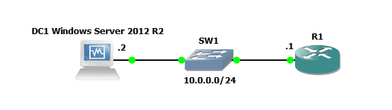
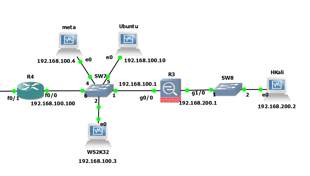
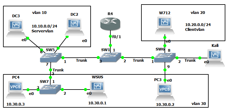
As with all my labs a picture paints a thousand words so here is the GNS3 Network topology we will be using, this is also being used for 802.1x which will be covered in later post:

Cisco AAA Authentication with RADIUS against Active Directory GNS3 Topology

So here is quick run down on the gear we will be using just for this lab:

R1: Cisco IOS (C7200-ADVENTERPRISEk9-M), Version 15.2(4)S4

Server 2012 DC: Windows Server 2012 R2 ( Active Directory Domain Services and Network Policy Server role.

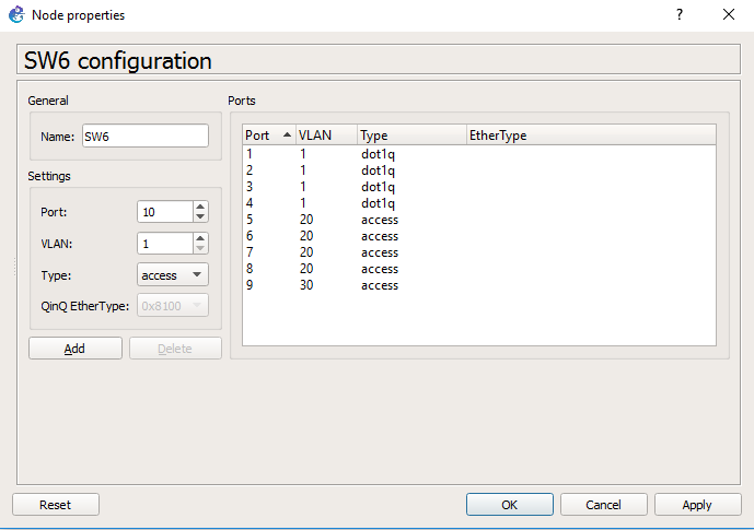
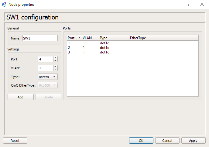
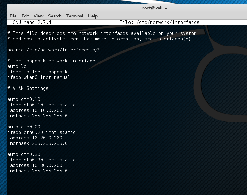
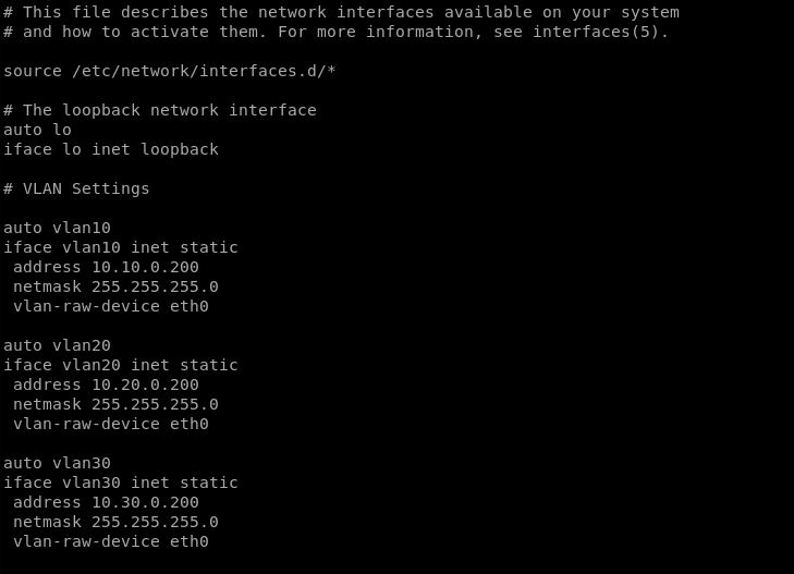
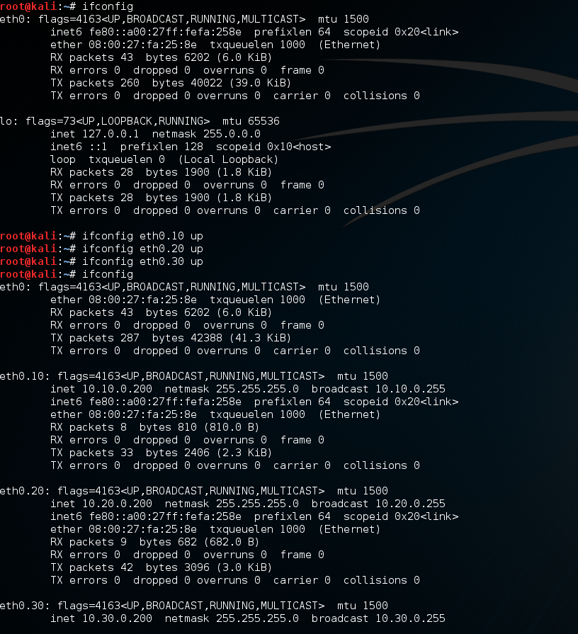
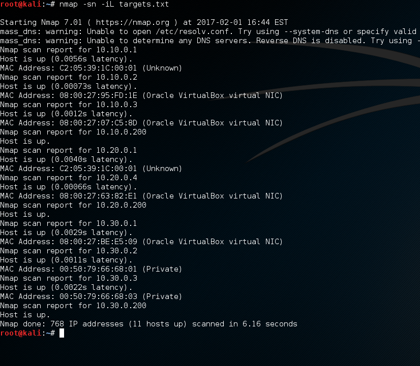
Just to demonstrate a lab as simple as the below could also be used to test this:

radius lab

Active Directory Configuration:

I will be assuming that AD and the NPS role have already been installed. Prior to jumping into the NPS configuration you will need to create an AD group for the users that will be logging into the Cisco equipment, add a couple of test users to this group. In my case I have simply created a group called ‘Radius’ and have added the user ‘Adam’.

Open the NPS console.

Right click on the NPS(Local) tree node and select ‘Register server in Active Directory’:

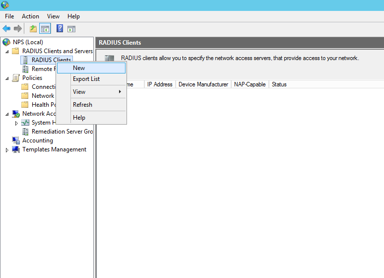
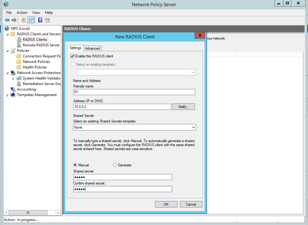
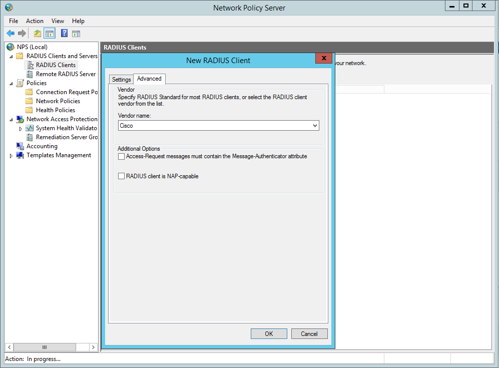
Now create the Radius clients, in our this case this is R1:

Radius Clients, New

New Radius Client Settings

New Radius Client Advanced Screen


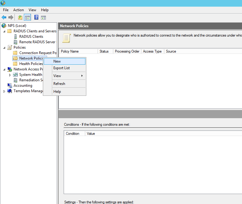
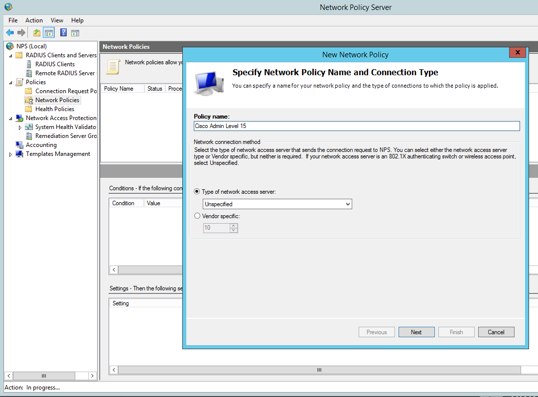
Now we need to configure the Network policy:

New Network Policy

New Network Policy name

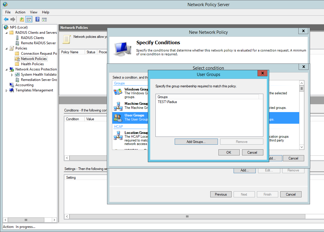
Add our ‘Radius’ AD group. You can tighten the control here by specifying further conditions such as the ‘friendly name’ (R1)  or the local IPV4 address of the radius client, in a production environment you would want to lock this down further for now we are just going to add the the user group to authenticate:

New Network Policy - Add

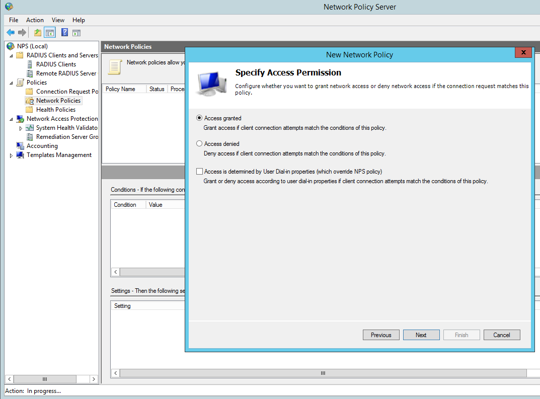
Grant Access for this group:

New Network Policy Access Granted

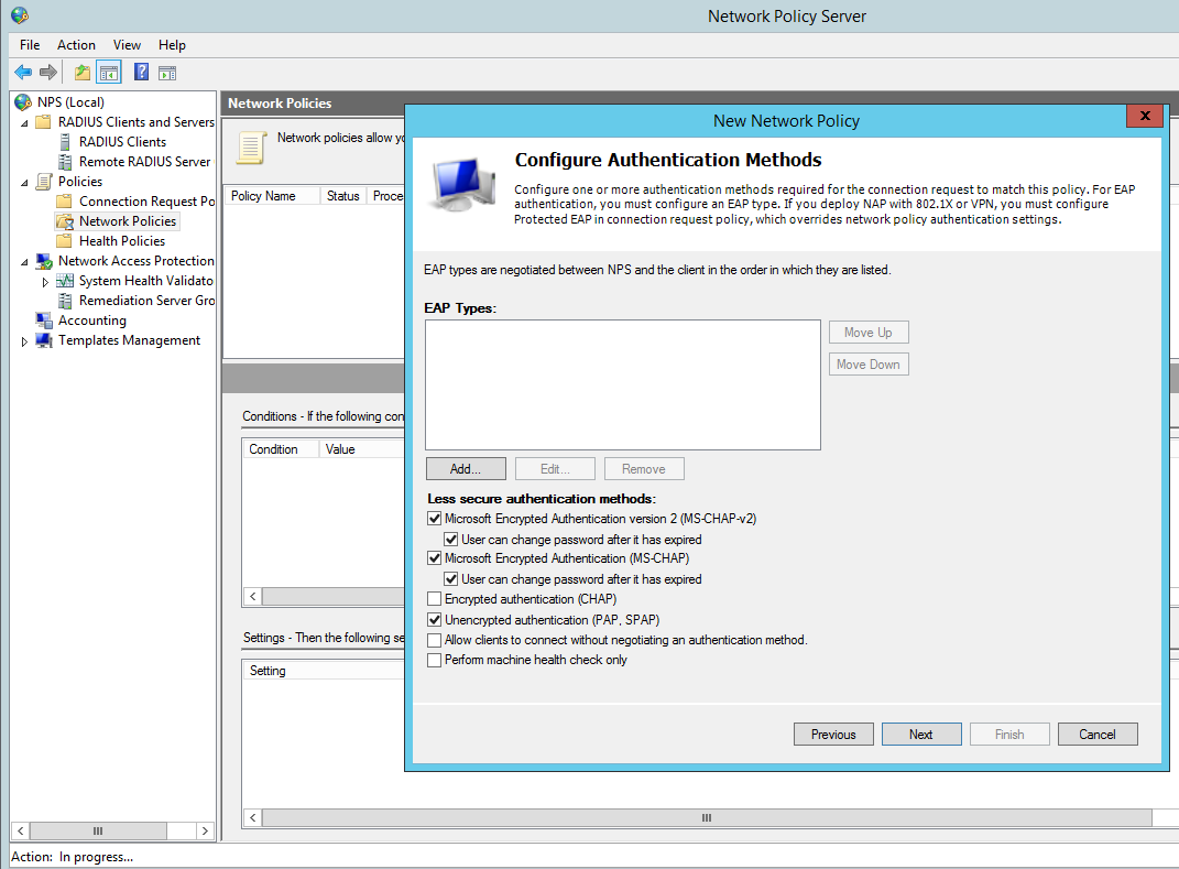
Configure the appropriate authentication methods:

New Network Policy - Configure Authentication Methods

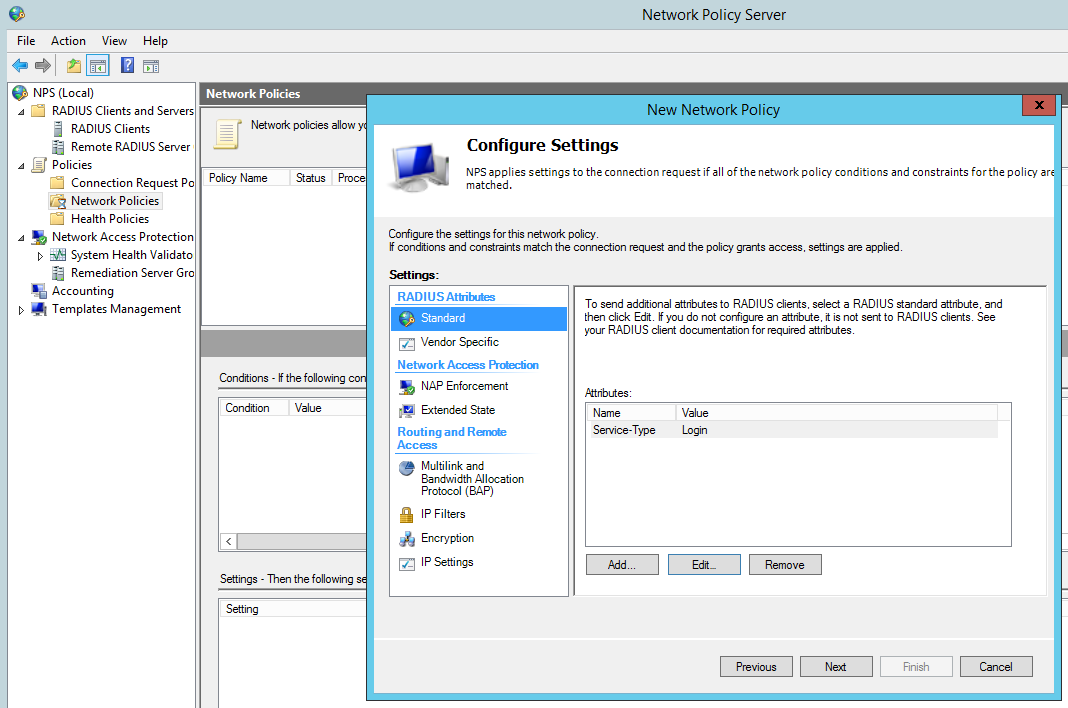
Change the Standard Radius Attributes by removing ‘Framed-Protocol – PPP’. Edit the ‘Service-Type’ value to ‘Login’:

New Network Policy - Standard Radius Attributes

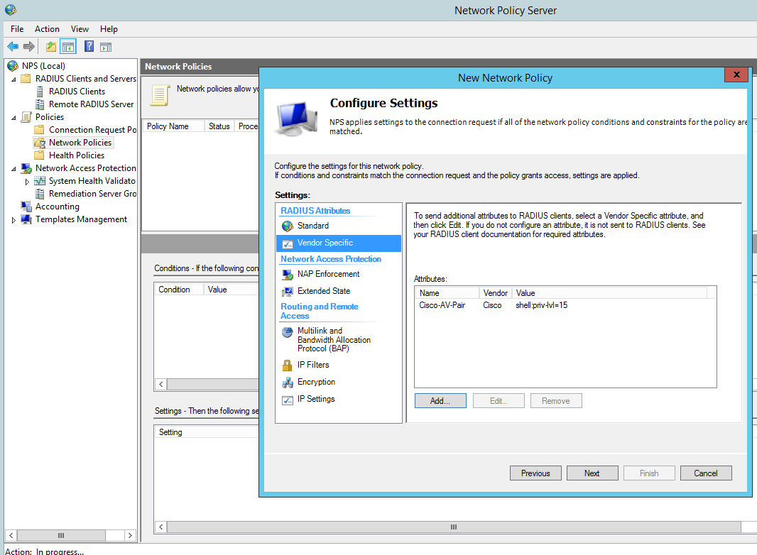
Add a Vendor specific attribute, this allows the radius server to pass the privilege level though the cisco router which we shall see later in the debugging. The value needs to read ‘shell:priv-lvl=15′.

You can create several policies for the different privilege levels. For example you could create a group in AD called ‘Cisco Users Priv 1’, associate this group to a policy and in the below option use the value ‘shell:priv-lvl=1′. When that user logs in the policy will match that user and the NPS use the matched policy passing privilege level 1 through to the router or switch.
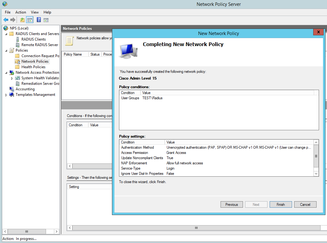
New Network Policy - Vendor Specific Radius Attributes

Then Finish:

New Network Policy - Finish

Cisco IOS configuration

Create a a user with privilege level 15, we wil use this as our fall back should the router not be able to contact the radius server it will use the local AAA database.

R1(config)#username Admin privilege 15 secret cisco12345

Enable AAA:

R1(config)#aaa new-model

Now we will setup the main parts to the radius configuration, tell the switch we would like to use radius and the group RAD_SERVERS:

R1(config)#aaa group server radius RAD_SERVERS

Specify the radius server that we would like to use in our case 10.0.0.2 is our NPS, the auth and acc ports and also the secure key we used:

R1(config-sg-radius)#server-private 10.0.0.2 auth-port 1812 acct-port 1813 key cisco
R1(config-sg-radius)#exit

Specify that for  the default login  for authentication an authorization that we want to use the group called RAD_SERVERS that we have just created and if that fails we use the local database. This is particularly important so we do not lock ourselves out on the router:

R1(config)#aaa authentication login default group RAD_SERVERS local
R1(config)#aaa authorization exec default group RAD_SERVERS local if-authenticated

All together this looks like the below:

R1(config)#aaa group server radius RAD_SERVERS
R1(config-sg-radius)#server-private 10.0.0.2 auth-port 1812 acct-port 1813 key cisco
R1(config-sg-radius)#exit
R1(config)#aaa authentication login default group RAD_SERVERS local
R1(config)#aaa authorization exec default group RAD_SERVERS local if-authenticated
R1(config)#aaa authorization console

We can test simply by logging out and back in.

Troubleshooting

It obviously goes without saying you need to test the authentication to the Radius server, exit right out of the console and log back in using your AD credentials.

If all has been configured correctly you should be able to login. its also worth testing the fall back option configured for local AAA authentication. We can do this just simply stopping the NPS service then try the local credentials, again all being configured correctly you should be able to login.

There are a few useful debugging commands we can use  to monitor and troubleshoot the authentication these being:

R1#debug aaa authentication
AAA Authentication debugging is on
R1#debug aaa authorization
AAA Authorization debugging is on
R1#debug radius
Radius protocol debugging is on
Radius protocol brief debugging is off
Radius protocol verbose debugging is off
Radius packet hex dump debugging is off
Radius packet protocol debugging is on
Radius elog debugging debugging is off
Radius packet retransmission debugging is off
Radius server fail-over debugging is off
Radius elog debugging debugging is off
R1#

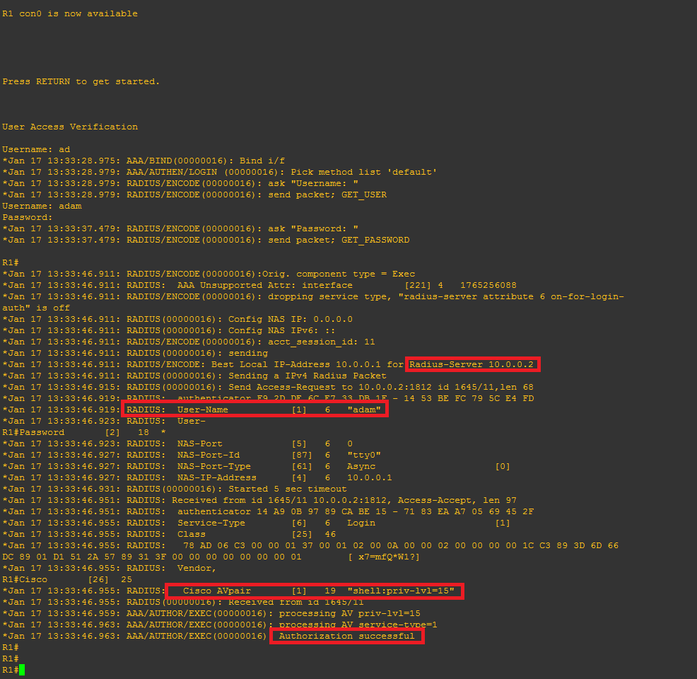
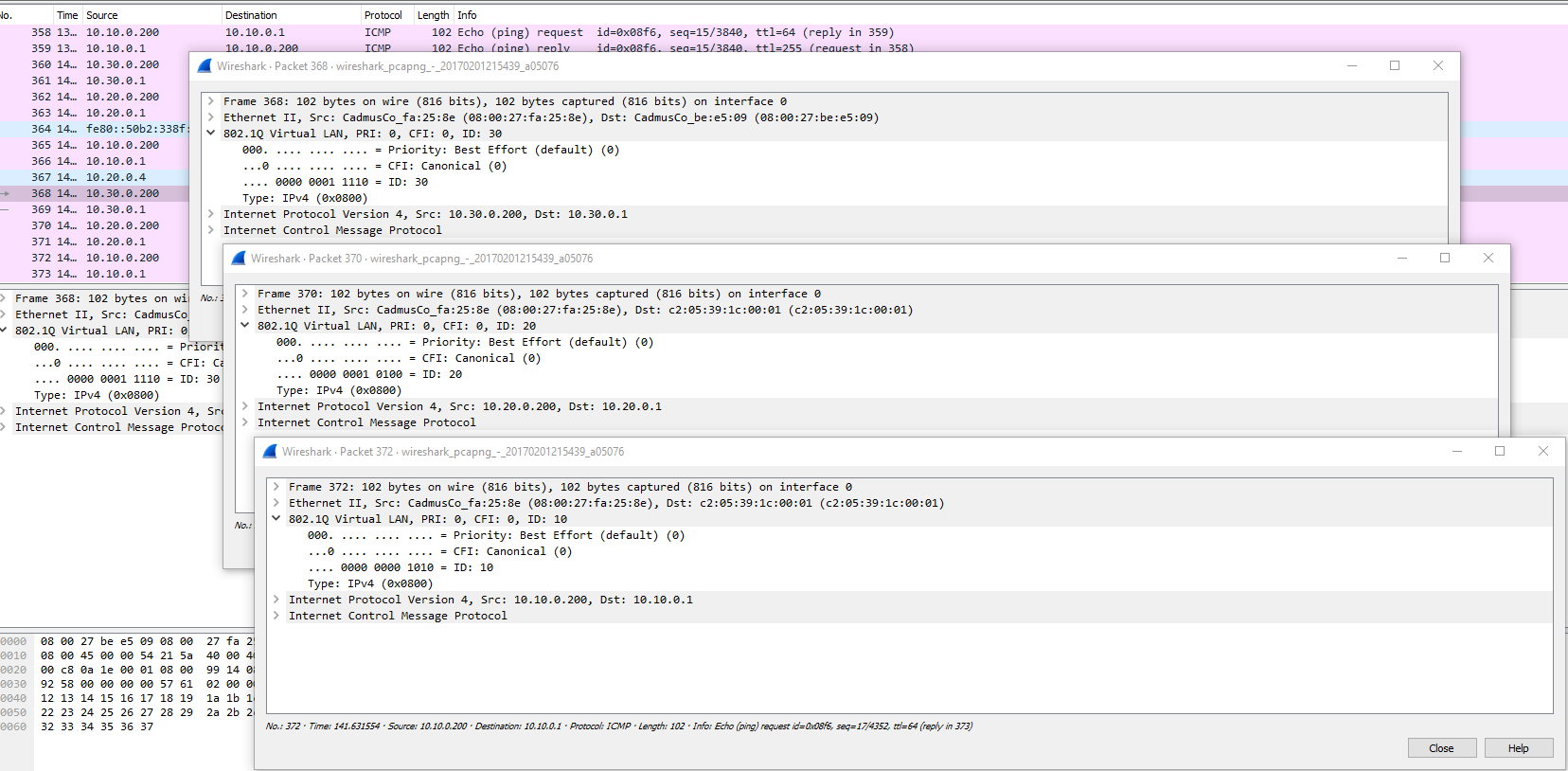
This time when we login we can see the debug information for an attempted login, it should look similar to this, note the highlighted area’s:

radterm

I hope this has been informative.