Ubuntu 14.04 Syslog Server

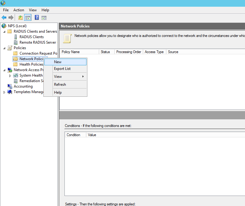
A quick and simple Ubuntu 14.04 Syslog Server with rsyslog for Network Devices.

In this post I going to run through creating a quick a simple Ubuntu 14.04 Syslog Server. Logging events is an important part of secure network configuration. The messages provided by devices such as switches, routers, firewalls and number of other devices provide a huge amount of information to systems administrators when a specific event has occurred and steps need to be traced. This could be for diagnosing a problem or looking at the activity of a potential attacker. When syslogging is setup it allows system administrators to respond better to incidents due to having the information readily available. Shipping the logs off to a remote server allows them to be safely stored without fear of them being deleted due to an attacker compromising the device but also the device being restricted due to small amount of storage space usually allocated.

In this post we are going to setup a syslog server on Ubuntu 14.04. Ubuntu uses rsyslog for its logging you can read all about this here, I’m just going to cover some of the basics to get you up and running, the idea here being that you have something to work on and take to the next level.

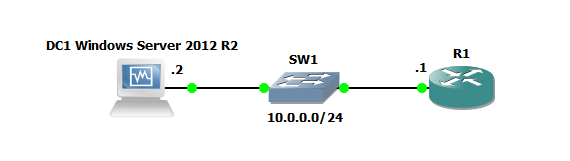
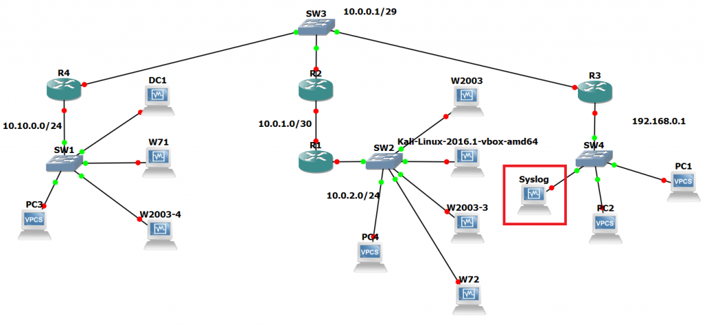
The below network diagram whilst may seem overly complicated, serves us well for this scenario and gives us our network and devices that we want to collect data from. In this scenario we want to collect logs from the routers. The platform we are going to test this out in is GNS3, truth be told it was a lab I had machines active for so though, meh… why not drop a syslog server in.

Ubuntu Syslog Server Network

There are essentially three steps I’m going to walk you through:

1. Configure the /etc/rsyslog.conf to accept remote incoming UDP syslog messages
2. Create and configure a conf file in /etc/rsyslog.d/30-cisco.conf. This is a new file we are going to create which specifies some rules on what we want to do with our messages if they come from different devices. You can add the rules to the rsyslog.conf file however creating a seperate conf file is the neater option in my opinion.
3. Change permissions of the /var/log/ directory so syslog user can make changes, create files etc.
4. Restart rsyslog with : sudo service rsyslog restart.
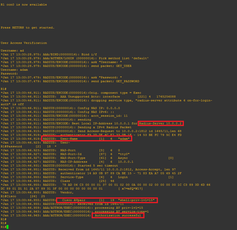
5. Test with our Cisco devices.

So taking our completely standard Ubuntu 14.04 install find our rsyslog.conf file in /etc/ and uncomment the following lines with our favourite text editor in my case ‘nano’:

$ModLoad imudp
$UDPServerRun 514

If you scroll down towards the bottom of the file we can see that it references to use all ‘conf’ files under /etc/rsyslog.d/ including where the default rules are kept in 50-default.conf.

Create/touch a new file calling it ’30-cisco.conf’, since we are only collecting syslog info for cisco devices on this occasion we shall chose this name. Append the file with the following lines of code:

# This rule runs in FRONT of the local/regular rules
# The below line sets a variable for the hostname and Cisco directory.

$template HostBasedLog,"/var/log/cisco/%HOSTNAME%.log"

# This creates a separate log file for each device

if $fromhost-ip == ‘192.168.0.1’ then -?HostBasedLog
& ~
if $fromhost-ip == ‘10.0.0.2’ then -?HostBasedLog
& ~

The above code sets up a template which creates the ‘cisco’ directory and also a log file using the hostname of the device the messages have come from.

From here we set the permsisions of the log directory for syslog service with ‘cd /var && sudo chown syslog:syslog log’

Restart the rsyslog service:  ‘service rsyslog restart’

All that is left to do is configure our cisco devices to ship logs off to our syslog server. For a typical cisco router or switch we can simple do this from a conf t prompt with ‘logging x.x.x.x’ also setting desired trap levels with: ‘logging trap debugging’ for example.

There it is, a simple syslog server, as said previously this is just something to get you started with. The next level to think about is rotation of log files, backups secure transfer of the log files through TLS which rsyslog supports.

Cisco AAA Authentication with RADIUS against Active Directory 2012 NPS

AAA and RADIUS through the Network Policy Server (NPS) role in Windows Server 2012 R2

I thought I would cover a quick post to demonstrate setting up Active Directory authentication for a Cisco router or switch IOS login. This will be using AAA and RADIUS through the Network Policy Server (NPS) role in Windows Server 2012 R2 to authenticate users in Active Directory on Cisco IOS devices.

As with all my labs a picture paints a thousand words so here is the GNS3 Network topology we will be using, this is also being used for 802.1x which will be covered in later post:

Cisco AAA Authentication with RADIUS against Active Directory GNS3 Topology

So here is quick run down on the gear we will be using just for this lab:

R1: Cisco IOS (C7200-ADVENTERPRISEk9-M), Version 15.2(4)S4

Server 2012 DC: Windows Server 2012 R2 ( Active Directory Domain Services and Network Policy Server role.

Just to demonstrate a lab as simple as the below could also be used to test this:

radius lab

Active Directory Configuration:

I will be assuming that AD and the NPS role have already been installed. Prior to jumping into the NPS configuration you will need to create an AD group for the users that will be logging into the Cisco equipment, add a couple of test users to this group. In my case I have simply created a group called ‘Radius’ and have added the user ‘Adam’.

Open the NPS console.

Right click on the NPS(Local) tree node and select ‘Register server in Active Directory’:

Now create the Radius clients, in our this case this is R1:

Radius Clients, New

New Radius Client Settings

New Radius Client Advanced Screen


Now we need to configure the Network policy:

New Network Policy

New Network Policy name

Add our ‘Radius’ AD group. You can tighten the control here by specifying further conditions such as the ‘friendly name’ (R1)  or the local IPV4 address of the radius client, in a production environment you would want to lock this down further for now we are just going to add the the user group to authenticate:

New Network Policy - Add

Grant Access for this group:

New Network Policy Access Granted

Configure the appropriate authentication methods:

New Network Policy - Configure Authentication Methods

Change the Standard Radius Attributes by removing ‘Framed-Protocol – PPP’. Edit the ‘Service-Type’ value to ‘Login’:

New Network Policy - Standard Radius Attributes

Add a Vendor specific attribute, this allows the radius server to pass the privilege level though the cisco router which we shall see later in the debugging. The value needs to read ‘shell:priv-lvl=15′.

You can create several policies for the different privilege levels. For example you could create a group in AD called ‘Cisco Users Priv 1’, associate this group to a policy and in the below option use the value ‘shell:priv-lvl=1′. When that user logs in the policy will match that user and the NPS use the matched policy passing privilege level 1 through to the router or switch.

New Network Policy - Vendor Specific Radius Attributes

Then Finish:

New Network Policy - Finish

Cisco IOS configuration

Create a a user with privilege level 15, we wil use this as our fall back should the router not be able to contact the radius server it will use the local AAA database.

R1(config)#username Admin privilege 15 secret cisco12345

Enable AAA:

R1(config)#aaa new-model

Now we will setup the main parts to the radius configuration, tell the switch we would like to use radius and the group RAD_SERVERS:

R1(config)#aaa group server radius RAD_SERVERS

Specify the radius server that we would like to use in our case 10.0.0.2 is our NPS, the auth and acc ports and also the secure key we used:

R1(config-sg-radius)#server-private 10.0.0.2 auth-port 1812 acct-port 1813 key cisco
R1(config-sg-radius)#exit

Specify that for  the default login  for authentication an authorization that we want to use the group called RAD_SERVERS that we have just created and if that fails we use the local database. This is particularly important so we do not lock ourselves out on the router:

R1(config)#aaa authentication login default group RAD_SERVERS local
R1(config)#aaa authorization exec default group RAD_SERVERS local if-authenticated

All together this looks like the below:

R1(config)#aaa group server radius RAD_SERVERS
R1(config-sg-radius)#server-private 10.0.0.2 auth-port 1812 acct-port 1813 key cisco
R1(config-sg-radius)#exit
R1(config)#aaa authentication login default group RAD_SERVERS local
R1(config)#aaa authorization exec default group RAD_SERVERS local if-authenticated
R1(config)#aaa authorization console

We can test simply by logging out and back in.

Troubleshooting

It obviously goes without saying you need to test the authentication to the Radius server, exit right out of the console and log back in using your AD credentials.

If all has been configured correctly you should be able to login. its also worth testing the fall back option configured for local AAA authentication. We can do this just simply stopping the NPS service then try the local credentials, again all being configured correctly you should be able to login.

There are a few useful debugging commands we can use  to monitor and troubleshoot the authentication these being:

R1#debug aaa authentication
AAA Authentication debugging is on
R1#debug aaa authorization
AAA Authorization debugging is on
R1#debug radius
Radius protocol debugging is on
Radius protocol brief debugging is off
Radius protocol verbose debugging is off
Radius packet hex dump debugging is off
Radius packet protocol debugging is on
Radius elog debugging debugging is off
Radius packet retransmission debugging is off
Radius server fail-over debugging is off
Radius elog debugging debugging is off
R1#

This time when we login we can see the debug information for an attempted login, it should look similar to this, note the highlighted area’s:

radterm

I hope this has been informative.

IPV6 and RIP GNS3 Lab

I decided to to look into configuring a quick simple IPV6 lab in GNS3 using RIP. I put together the following lab using the RIP routing protocol for ease of use. The lab consists of  3 routers multiple interfaces, 3 subnets, 3 PC’s and switches for endpoint connectivity, I find its easier to use the virtual switches if I want to expand the lab later. The routers are the using the c7200-adventerprisek9-mz.152-4.S4 image and the PC’s are simply the virtual PCs (VPCS) from GNS3 again for ease of use. I do normally prefer to connect an actual operating system as PC’s as I find it more realistic however as we are just testing connectivity and routing the VPCS option is a good fit here and light on system resources.

Below is the simple topology:

RIP and IPV6 lab
RIP and IPV6 lab

Some of the basic configuration for RIP and IPV6 is show below for R1. This can then be replicated across the other routers and interfaces changing the IPV6 subnet ID and Interface ID as you go along. Using Global IPV6 addresses with a made up subnet ID.

Straight in the configuration starting in global configuration mode on R1:

R1(config)#ipv6 unicast-routing
R1(config)#int fa0/0
R1(config-if)#ipv6 address 2001:db8:6783:120::1/64
R1(config-if)#no shutdown

Verify the interface:

verify the ipv6 interface configuration.

Note the new IPV6 Link Local address that has been automatically assigned to the interface when it was brought up, the closest thing to explaining for now is the 169.254.x.x/16 address asinged by APIPA. The Link Local address is made of the first 10 bits (identifiable as the Link Local FE80) the other 54 bits being Zeros (::) and the remaining 64 bits being made up of the MAC address and FFFE slotted in the middle. 🙂

Onto the routing:

R1(config)#ipv6 router rip RIP1
R1(config)#int fa0/0
R1(config-if)#ipv6 rip RIP1 enable

The router will then advertise its routes through the enabled interface for RIP1 using rip and likewise for R2 and  R3. Once R3 has been configured 30 seconds later a quick check of the routing table from R1 should display:

IPV6 rip routing table

We can see the advertised routes for rip, also notice that the advertised route is via its IPV6 Link Local address starting with FE80.

A quick check from PC3 to R1 and PC4 further verifies  connectivity through IPV6 and rip configuration:

Checking IPv6 endpoint connectivity from PC3 to PC1.
Checking endpoint connectivity from PC3 to PC1.

Interesting, more to come from IPV6 in the future for sure.

CCNA Security – Implementing Cisco Network Security Lab

I thought I would share with you the Lab I have been mostly working with for CCNA  Security (CCNAS) – Implementing Cisco Network Security (210-260) exam that I have recently took and passed. I have also used several smaller lab setups for specific testing however this is the main lab to piece everything together.

CCNAS - Implementing Cisco Network Security Lab
CCNAS – Implementing Cisco Network Security Lab

The lab has been built to accommodate the many elements on the exam and covers off most of the practical procedures that you need to be comfortable with. Using GNS3 and VirtualBox we are able to lab most of the practical exercises bar the L2 switching portions which I achieved through physical equipment (Catalyst 3750, 3550 x2 and 2950 switches). The exam does cover many topics in theory that you must know, these aren’t covered here, however can be found on the Cisco website.

The lab contains several client machines for managing the routers and ASA firewalls from putty, cisco configuration professional and ASDM as well as testing PAT through the ASA with a breakout to the internet. There is an Active Directory Domain Controller with the Network Access Protection role installed for use with AAA/radius and NTP. A separate syslog server. A DMZ with web server for testing NAT and outside firewall rules. There is also an ASA 5520 at each of the three sites for testing VPN site-to-site Ipsec connections, clients at all sites for testing end to end connectivity. There is also an outside remote client for testing the Anyconnect and client-less vpn options which takes advantage of the AAA radius service.

Using this lab we are able to address the following practical elements for the CCNAS exam:

2.0 Secure Access

2.1   Secure management

  • 2.1.b Configure secure network management
  • 2.1.c Configure and verify secure access through SNMP v3 using an ACL
  • 2.1.d Configure and verify security for NTP
  • 2.1.e Use SCP for file transfer

2.2 AAA concepts

  • 2.2.b Configure administrative access on a Cisco router and ASA using RADIUS
  • 2.2.c Verify connectivity on a Cisco router and ASA to a RADIUS server
3.0 VPN

3.2 Remote access VPN

  • 3.2.a Implement basic clientless SSL VPN using ASDM
  • 3.2.b Verify clientless connection
  • 3.2.c Implement basic AnyConnect SSL VPN using ASDM
  • 3.2.d Verify AnyConnect connection
  • 3.2.e Identify endpoint posture assessment

3.3 Site-to-site VPN

  • 3.3.a Implement an IPsec site-to-site VPN with pre-shared key authentication on Cisco routers and ASA firewalls
  • 3.3.b Verify an IPsec site-to-site VPN
4.0 Secure Routing and Switching

4.1 Security on Cisco routers

  • 4.1.a Configure multiple privilege levels
  • 4.1.b Configure Cisco IOS role-based CLI access
  • 4.1.c Implement Cisco IOS resilient configuration

4.2 Securing routing protocols

  • 4.2.a Implement routing update authentication on OSPF
5.0 Cisco Firewall Technologies

5.3 Implement NAT on Cisco ASA 9.x

  • 5.3.a Static
  • 5.3.b Dynamic
  • 5.3.c PAT
  • 5.3.d Policy NAT
  • 5.3 e Verify NAT operations

5.4 Implement zone-based firewall

  • 5.4.a Zone to zone
  • 5.4.b Self zone

5.5 Firewall features on the Cisco Adaptive Security Appliance (ASA) 9.x

  • 5.5.a Configure ASA access management
  • 5.5.b Configure security access policies
  • 5.5.c Configure Cisco ASA interface security levels
  • 5.5.d Configure default Cisco Modular Policy Framework (MPF)

Well what next, CCNP Security of course.

Labs and Virtualization

Anybody that works in IT that really wants to progress will know and will have experienced the value of labs and virtualization. Being able to test an idea or for learning in a virtual lab, its essential whether it be in Linux or Windows. Being able to through up a webserver to test a setting or a domain controller to test a group policy. Whether its on a full blown ESXi deployment or just virtual box. The aim of this page is to go through some of the virtualization options that are available to the home user, and dig into the software and hardware that’s required. Check out the following page for some hint and tips: https://www.adamcouch.co.uk/labs-projects/labs-and-virtualization/

Labs and Virtualization The great hypervisor! take your pick.